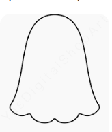
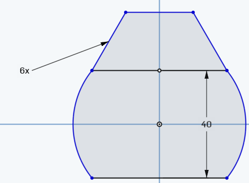
Do Your best to draw this shape. You have the whole period to work on this.
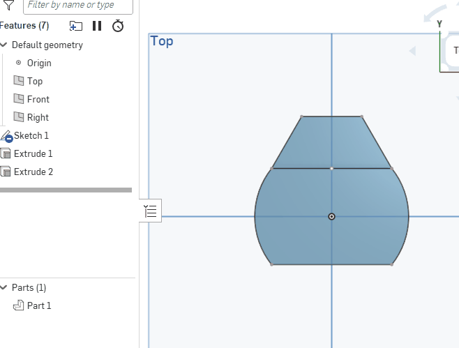
We will work on the parts studio again on Monday.

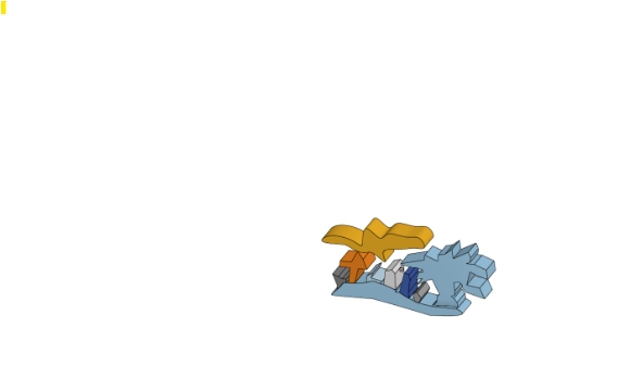
Some Examples:
Do Your best to draw this shape. You have the whole period to work on this.
We will work on the parts studio again on Monday.
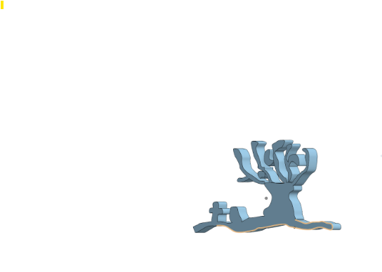
Some Examples:
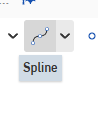
Use the spline tool to draw 1 shape from here.
Extra credit if you draw 2 shapes. To get extra credit, these must be drawn well!
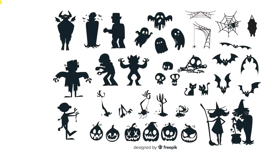
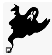
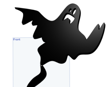
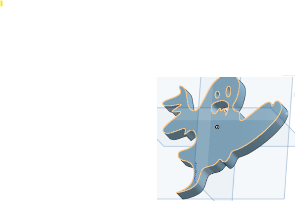
Use the Spline tool to make a picture of a ghost
This is worth 5 points. You can see examples of grades a
3 out of 5
4 out of 5

5 out of 5
Or you can do a comparable one
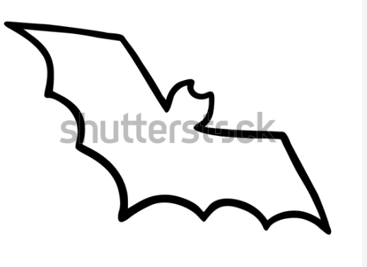
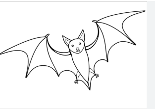
Below is what some students have already done :
Step 1) Use the Spline tool to create a bat shape. The more complex the shape, the more the points.
Picture 1 : 4/5
Picture 2 : 5 out o 5
You can also pick a more complicted or different picture
Do an extrude on it.
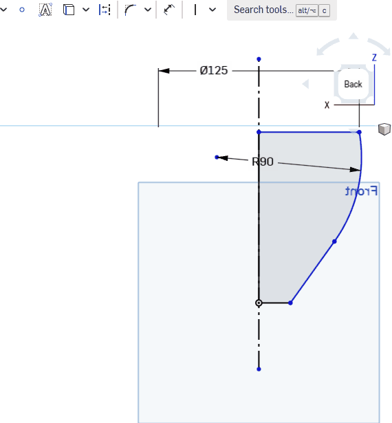
How to Dimension over a Construction (mirror line)
 \
\
After offset, make sure you’re points are coincident– Watch the end carefully!
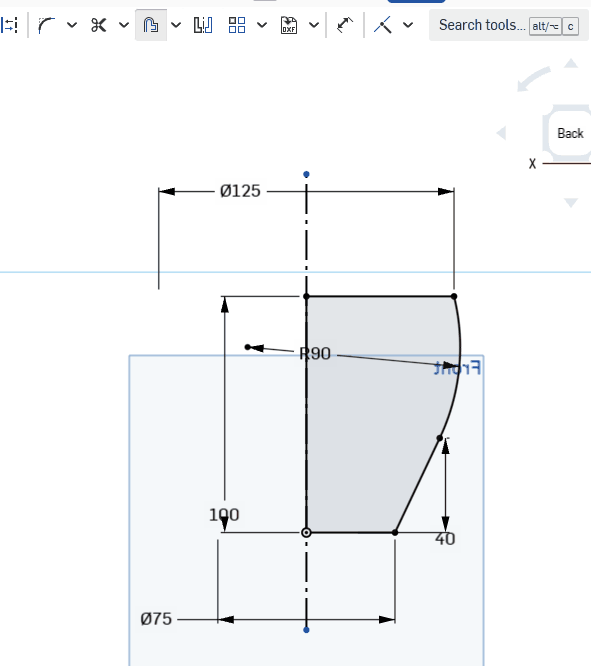
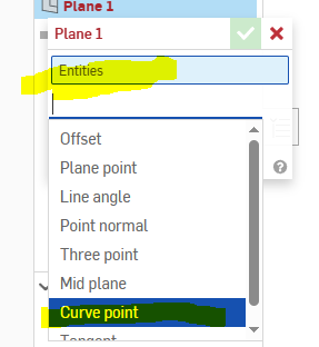
Curve Point option of plane
Step 1) Open up any do-now that we have already done . Delete the prior sketch
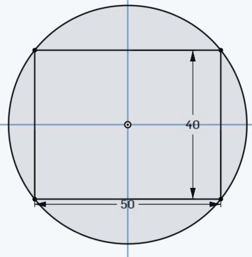
Step 2) Create a rectangle with a center on the origin and a height of 40 and width of 50
![]()
Step 3) Make a circle centered at the origin. The 4 points of the rectangle should be coincident with this circle. Resulting picture:
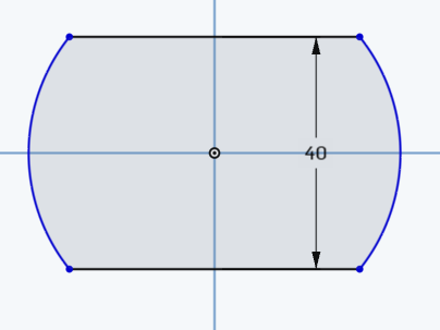
Step 4) Use the scissors tool to create this :
Step 5) Create a circumscribed polygon with 6 sides (hexagon). The 2 vertices should be coident with the points as shown below:
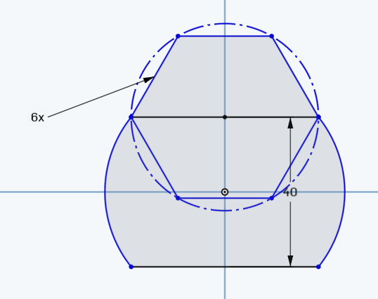
Step 6) Use the scissor tool to make this :
Step 7) Extrude the middle part by 50MM and the bottom remaining hexagonal part by 30 MM. to produce:
Step 8) take a screenshot and attach to google doc and then delete your work
Part II: Your own Revolve, Seep or Loft
Create at least 3 interconnected shapes (circle, arcs, rectangles etc..). Perform either a revolve, a loft or a sweep. I will give an extra credit point if yo udo a sweep or loft!
Do now
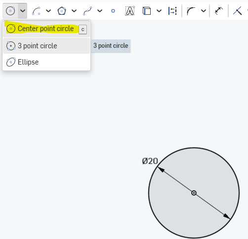
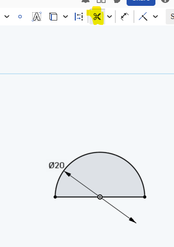
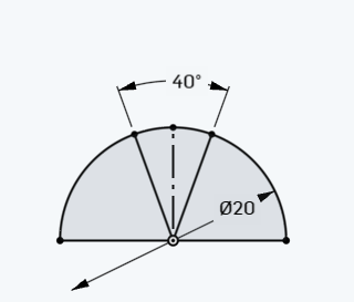
Step 1) Clear out an old do now. Create a center point circle with a radius of 20:
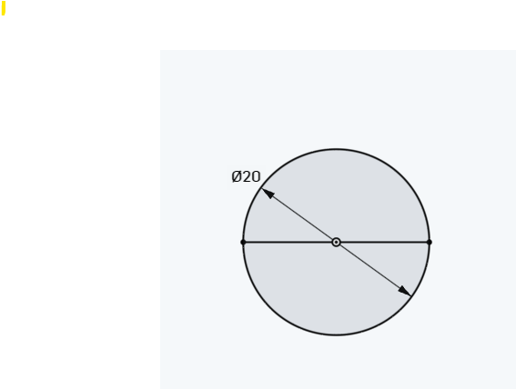
Step 2) Make a diameter
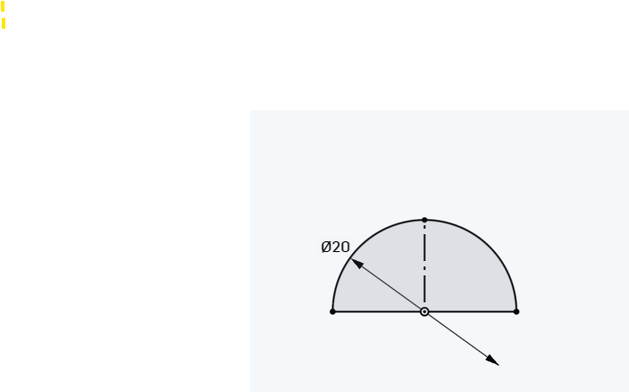
Step 3) Use the scissor tool to cut the bottom half of the circle off
Step 4) Make a vertical construction line right up the middle of the circle
step 5) Add 2 lines symmetric about the construction line
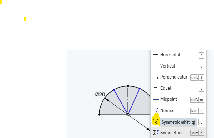
Step 6) the angle should be 40 . How to dimension an angle
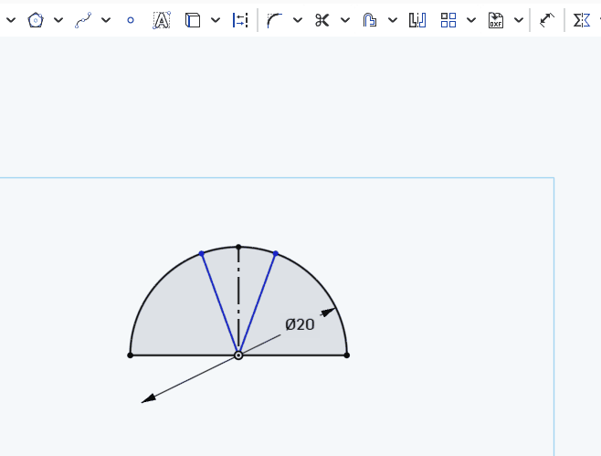
result :
step 7) Use the scissors tool to cut out the center arc.
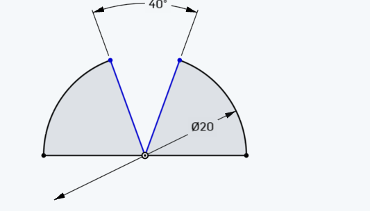
step 8) MIrror the shape over teh diameter:
Step 9) Extrude 1 half of shape by 45 MM
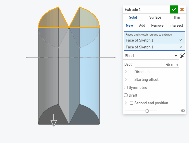
Step 10) Extrude the other half by 27 MM
Part II . Your own shape
After you take a screenshot of the above shape, do a different type of 3-d model. You can use anything else whether its a revolve, a sweep or a loft
To get full credit on this you must use either a sweep or a loft as your 2nd 3-d shape.
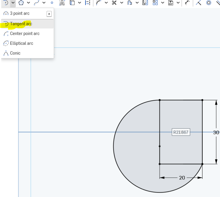
We are going to make 2 revolves
Step 1) create a 20×30 rectangle with centered at the origin. “Center point
Step 2) Add a 3 point arc using tangent
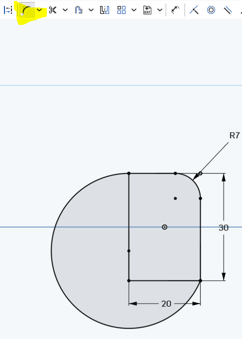
Step 3) Create a fillet with a radius of 7
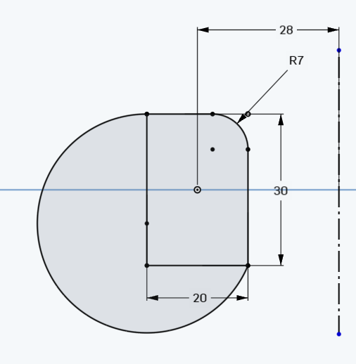
Step 4) Add a construction line , dimension it to 28 MM away from origin
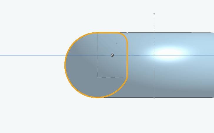
Step 5) Revolve the shape around the construction line to produce:
Step 6) Create a reference plane. Make sure you connect it to the top plane :
Step 7) Take a screenshot of the above shape and paste it in google doc
Step 8) Create an extrude of a complex shape. Your “complex shape” should be at least 3 parts (like a circle a rectangle and something else). Your extrude should go to 2 different heights
Take a final screenshot into the google doc
Step 1) open any prior do now and delete the sketch and restart
Step 2) make sure that the workspace units are MM
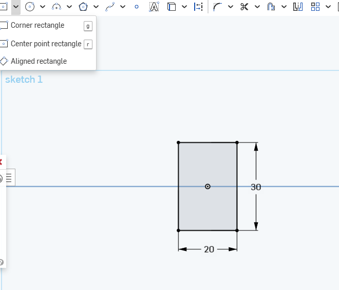
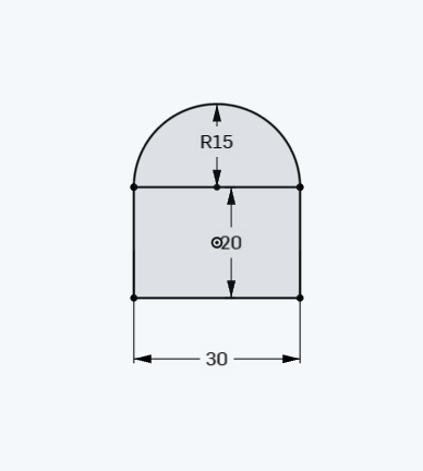
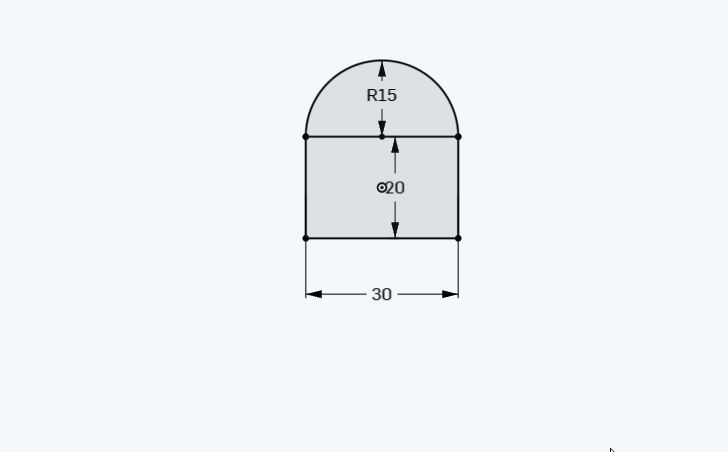
Step 3) create a rectangle with its center point as the midpoint on the origin. The rectangle should be 30 by 20. See video below
Step 4) Create a semicircle with a radius of 15 (use or or make a circle and cut half off with the scisoors tool
Step 5) Create an isosceles triangle like this (Dimensions do not have to be exactly like mine)
The remaining steps are up to your discretion
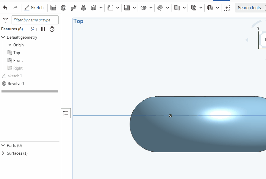
Part I . REVOLVE
Step 6) Create a line somewhere and revolve the shape around it
Part II) 2 Extrudes with your own shapews
Create a shape with multiple elements (maybe a circle and a rectangle) Create 2 extrudes with different heights like we did before
Screenshot and put in google classroom.
Step 1) open up any of our prior documents that we are done with and delete the prior work
Step 2) Create this sketch with these dimensions. The lines from the circle to the rectangle must be tangent to the circle.

Step 3) Extrude the smaller inside circle 50 mm:

Step 4) the outer circle and the rectangle should have a 25 MM extrude

Step 5) The connecting shape is a 10 MM extrude

Step 6) Create your own shape and do a revolve