Category Archives: DDP

Fillet and Shell

Units : MM

Step 1) Inscribed Triangle . Dimensioned to 22. Centered at origin

inscribed triangle

Step 2)  Make 1 vertex of triangle vertical with the origin. This will define the shape

inscribed triangle 2

Step 3)  This is what your shape should now look like :

inscribed triangle 3

Step 4) Use the scissor tool to delete the top 3rd of the circle

inscribed triangle 4

Step 5) Connect the 2 points (make sure it’s defined)

inscribed triangle 5


Step 6) Perform 2 extrudes (25 and 35). :

inscribed triangle 6

Step 7)  Fillet as shown:

inscribed triangle 7

Step 8)   Add a shell:

inscribed triangle 8


Step 9)  Final product:

inscribed triangle 9

Extrude Fillet Chamfer

Workspace Units: MM

Step 1) Create a new sketch on the front plan and create the following sketch. All share centered at the origin:

dimensioned shape

(Click image to enlarge)

Step 2) Extrude 1:

extrude 1

Step 3) If sketch 1 is hidden, make sure to show it

Step 4) Extrude 2:

extrude 2

Step 5)Fillet :

fillet1

Step 6) Add a chamfer:

chamfer

Result

extrude-fillet-chamfer

Angle, Symmetric, FIllet practice

Set document to MM

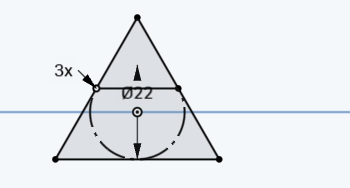
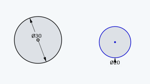
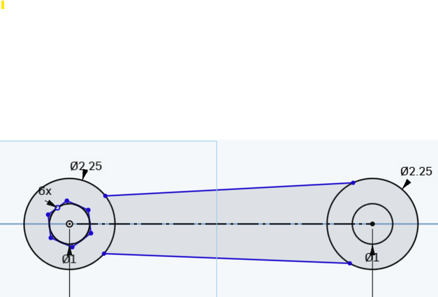
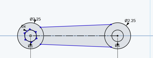
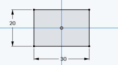
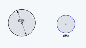
Step 1) Make a circle, centered at origin with a diameter of 30. Then create a circle with a diameter of 20 to its right.

twocircles1

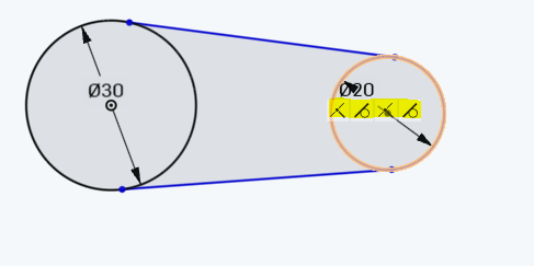
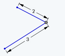
Step 2)  Connect the 2 circles with 2 lines coincident on to both circles. You should see the highlighted constraints when you mouseover either of them:

twocircles2

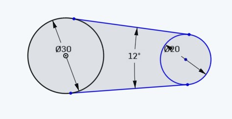
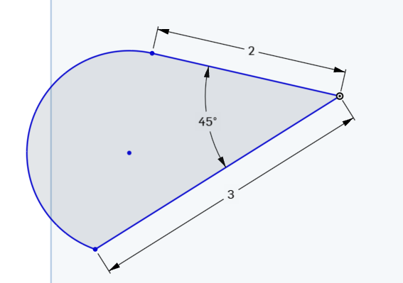
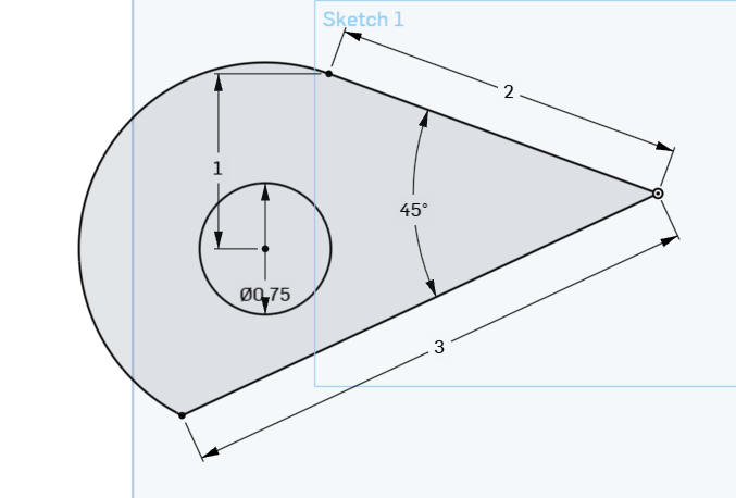
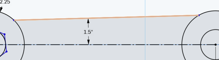
Step 3) Dimention the angle between the 2 lines to be 12 degrees. Make sure it’s the ANGLE , not the distance. If you’re not sure how to do that, watch this short animation.

twocircles12 degrees

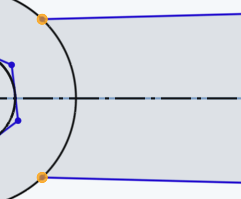
Step 4) Create a construction line connecting centers, then make the two lines symmetric to that line:

symmetric

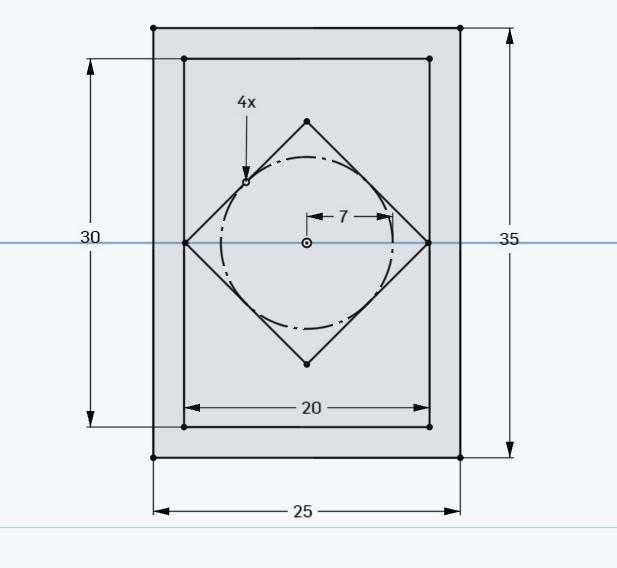
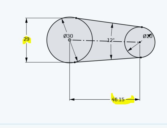
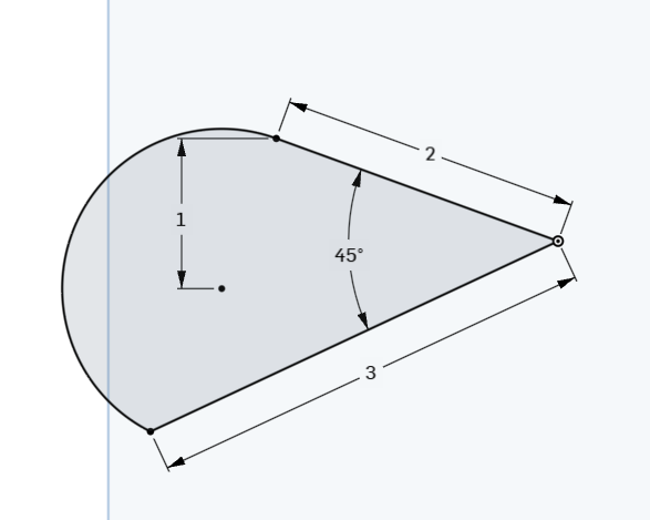
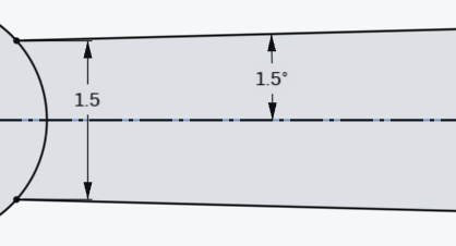
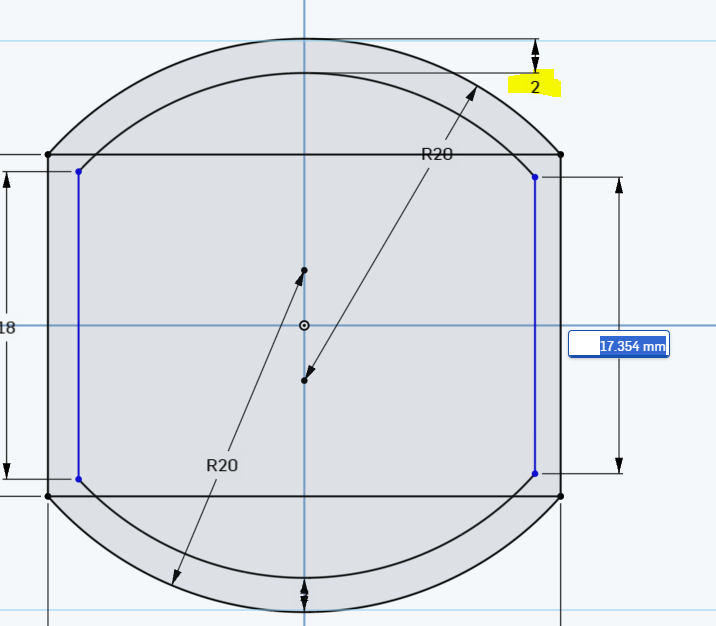
Step 5) Add the 2 dimensions shown . The shape should now be fully defined (all black)

twocircles4


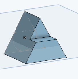
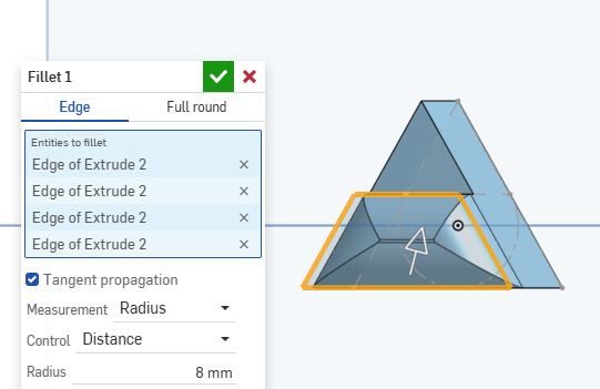
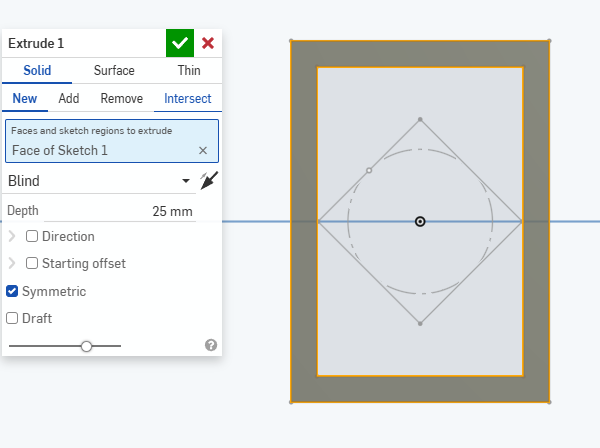
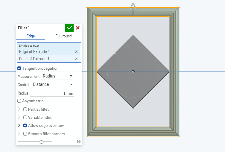
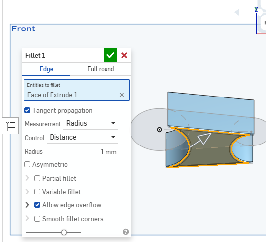
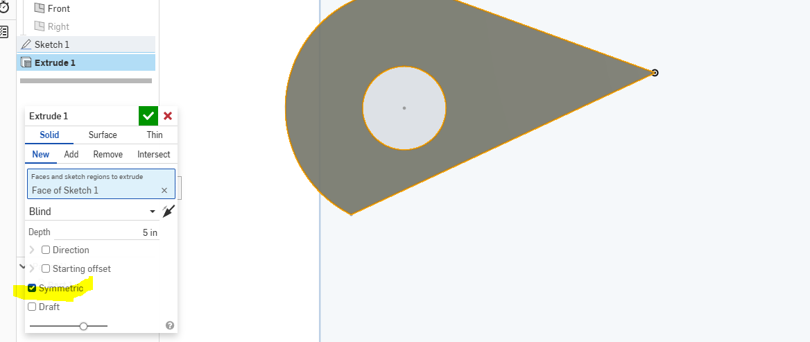
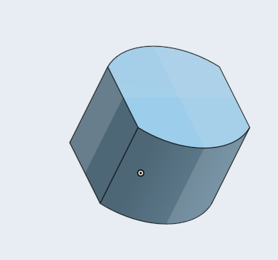
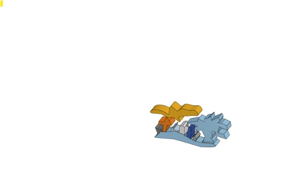
Step 6) Extrude the middle part by 15 . Symmetric extrude and then add a 1 MM Fillet:

extrude and fillet


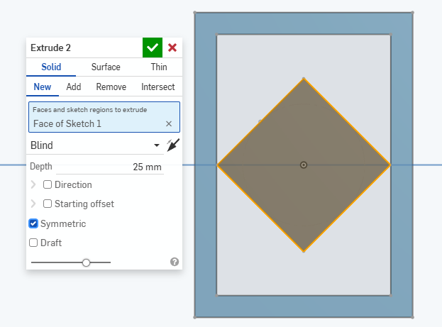
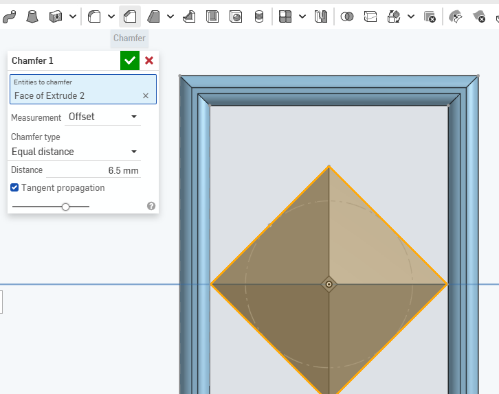
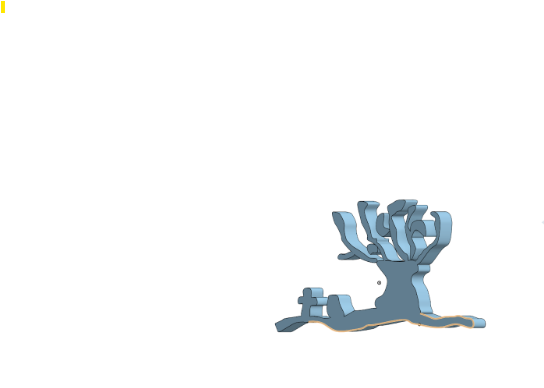
Step 7) Extrude th e2 circle by 30 MM (no pic. You should be able to do this on your own)

Lines and Angles and Symmetric Extrude

Step 1) Open up a new document.

Step 2) Create a line of length 2 from the origin and line of length 3 from the origin; something like . Their exact angle doesn’t matter, just something like :

2lines

Step 3) Create a 45 degree angle between the 2 line segments:

how-to-do-angle

Step 4) Connect the end points with a tangent arc:

tangent-arc

Step 5) Dimension the center of that arc with the point of top line as shown:

tangent-arc-dimensioned

Step 6) Create an inscribed circle as shown :

inscribed-circle

Step 7)  Create a symmetric extrudesymmetric-extrude2

Step 8) Finished product. Notice how the symmetric extrude goes up and goes down:

symmetric-extrude

Advanced Parts Design Tips I

Step 1)

lines should be larger on right side

tip_1

Step 2) Make the blue lines symmetric to the construction line

tip_2

Step 3)  Click on the top line and construction and dimension the 1.5 degree angle

tip_3

Step 4)  dimension the 2 left side points to 1.5

tip_4

Step 5) Resulting picture :

tip_5


Extrude with Offset

Step 1) Create a rectangle centered at the origin with a height of 20 and width of 30:

30by20rectangle

Step 2) add an arc as shown. Make sure it’s dimensioned :

30by20rectanglewarc

Step 3) Now the bottom:

30by20rectanglewarcNumba2


Step 4) Extrude the shape by 25MM:

extrude25mm

Step 5)  un-hide sketch 1

unhideSkettch1

Step 6)

Go into sketch 1 and create  2 MM offset on the top arc and on the bottom arc, then connect their endspoints with lines :

offset as 2

Step 7)

Final Result

final-result